
KFAS: Fanuc CNC Parts & Repair
![]()
![]()
![]()
![]()
![]()
Fanuc Series 0T/ 0M Troubleshooting Information/ Procedures/ Alarms
Fanuc 0TC/ 0MC Maintenance Manual: B-61395E
Fanuc 0TD/
0MD Maintenance Manual: B-62545E
Determining Program Memory Size
Alarm List and Description
Absolute Pulse Coder (APC) Alarms: Alarm 3n0 through 3n7 (n = 1 - 8)
Troubleshooting Steps
Alarm 3n0 (n = 1 to 8): Request for reference position return
Alarm 3n1 to 3n6: Absolute Pulse Coder is faulty
Alarm 3n7, 3n8: Absolute Pulse Coder Battery is low
Alarm
3n9: Serial Pulse Coder is abnormal
Servo Alarms: Alarm 400 through 495
Alarm 408: Serial Spindle link does not start normally
Alarm 409: Serial Spindle Alarm
Over travel Alarms 5n0 through 5n5, 520, 590, 591, 592, 593
System Alarm: 910 through 916, 920, 921, 922, 930, 940, 941, 945, 946, 950, 960, 998
Alarm 910 to 916: RAM Parity Error
Alarm 920, 921, 922: Watch dog alarm or RAM parity alarm
Alarm 941: Incorrectly installed Memory Printed Circuit Board
Alarm 945: Serial Spindle communication Error
Reader/Puncher RS232 interface alarm: Alarm 85 to 87
Check RS232 related parameter settings
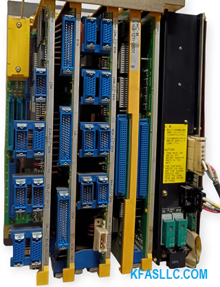
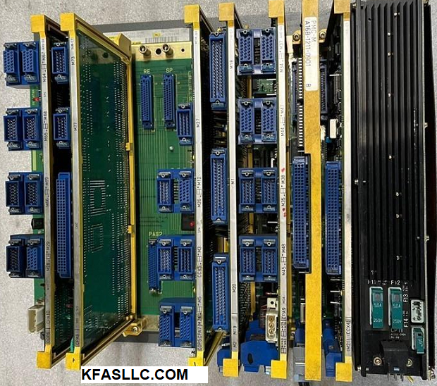
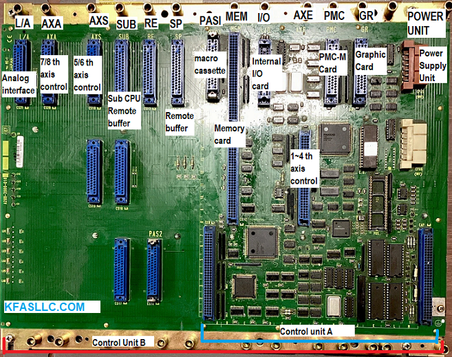
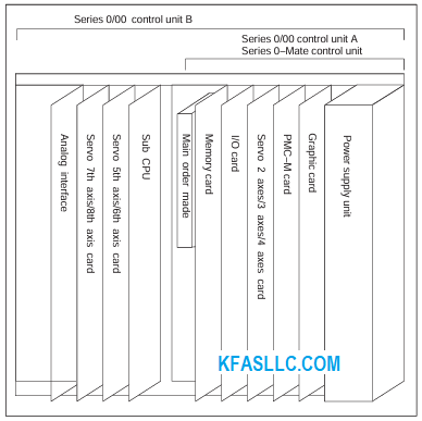
Master Board
A20B-1002-0360 16 bit Master Board A
A20B-2000-0170 32 bit Master Board A
A20B-1003-0750 16 bit Master Board B
A20B-2000-0180 32 bit Master Board B"
A20B-1003-0760
Memory Card
A16B-1212-0210 (OLD) S Analog
A16B-2201-0103 (NEW) Replaces A16B-1212-0210
A16B-1212-0216 (OLD) S Serial
A16B-2201-0101 (NEW) Replaces A16B-1212-0216
A16B-1212-0215 S Serial
I/O Board
A16B-1212-0222 (OLD) I/O Card C5
A16B-2203-0112 (NEW) Replaces A16B-1212-0222
A16B-1212-0221 (OLD) I/O Card C6
A16B-2203-0111 (NEW) Replaces A16B-1212-0221
A16B-1212-0220 (OLD) I/O Card C7
A16B-2203-0110 (NEW) Replaces A16B-1212-0220
A16B-1211-0946 I/O Card D6
A16B-1211-0945 I/O Card D7
Axis Control Card
A16B-2200-0221 2 axes 16 bit
A16B-2200-0361 2 axes 32 bit
A16B-2200-0391 2 axes w/ serial Pulse Coder
A16B-2200-0220 3/4 axes 16 bit
A16B-2200-0360 3/4 axes 32 bit
A16B-2200-0390 3/4 axes w/ serial Pulse Coder
Graphic Card
A16B-1211-0920 9" Mono, 14"Color
A16B-2200-0350 9"Color Hi Resolution
A16B-1211-0340 9"Color Low Resolution
MPG Interface Card
A16B-1210-0801
PMC-M
A16B-1211-0901 ROM Board Electric Interface
A16B-1211-0907 RAM Board Electric Interface
A16B-1211-0903 ROM Board Optical Interface
A16B-1211-0909 RAM Board Optical Interface
PMC-M (I/O LINK)
A16B-2200-0340 ROM Board
A16B-2200-0345 RAM Board
A16B-2200-0341 ROM Board
A16B-2200-0346 RAM Board
MDI/CRT Adapter
A02B-0086-C051 Without PMC-M
A02B-0086-C052 PMC-M ROM Board
A02B-0086-C053 PMC-M RAM Board
A02B-0086-C055 PMC-M ROM Board
A02B-0086-C056 PMC-M RAM Board
HS Remote Buffer
A16B-1211-0930 Hi Speed Remote Buffer
SUB CPU
A16B-2200-0320 Sub CPU Card
5/6 th Axis Card
A16B-2200-0330 for 16 bit CPU
A16B-2200-0370 for 32 bit CPU
A16B-2200-0371 for 32 bit CPU
5/6 th Axis Card (Serial Pulse Coder)
A16B-2200-0800 for 0TT Control
Analog Interface
A16B-1211-0961
7/8 th Axis Card
A16B-2200-0380 for 32 bit CPU
7/8 th Axis Card (Serial Pulse Coder)
A16B-2200-0790 0L Hispeed Machinnig
7th Axis Card
A16B-2200-0791 0L Control
Macro Casette
A02B-0091-C110 64KB Order Made Macro
A02B-0091-C112 128KB Order Made Macro
A02B-0091-C114 256KB Order Made Macro
A02B-0098-C116 512KB Order Made Macro
A02B-0098-C118 1MB Order Made Macro
Input Unit
A14B-0076-B001
A14B-0076-B023
Power Supply
A16B-1211-0850 Power Supply A
A16B-1212-0100 Power Supply A1
A16B-1212-0110 Power Supply B2
A16B-1211-0890 Power Supply C3
A16B-1212-0950 Power Supply
MDI/CRT 9 INCH
A86L-0001-0125 Keyboard
A86L-0001-0137 Full Keyboard
A20B-1001-0720 Soft Key
A98L-0001-0518/T F0T Keysheet
A98L-0001-0518/M F0M Keysheet
A98L-0001-0568/T F0T Full Keysheet
A98L-0001-0568/M F0M Full Keysheet
A98L-0001-0629 Soft Keysheet
A98L-0001-0660 EL Unit Soft Keysheet
A61L-0001-0093 9 Inch Monochrome CRT Unit
A61L-0001-0090 9 Inch Color CRT Unit
A61L-0001-0114 EL Display Unit
MDI/CRT 14 INCH
A86L-0001-0138 Key Board
A20B-1002-0320 Soft Key
A98L-0001-0569/T F0T Keysheet
A98L-0001-0569/M F0M Keysheet
A98L-0001-0630 Soft Keysheet
A61L-0001-0094 14 Inch Color CRT"
MMC MDI/CRT 14"
A20B-1002-0700 MMC Main CPU
A20B-1002-0710 Sub CPU
A20B-1001-0920 Back Panel
A20B-1001-0860 ROM File 512KB
A20B-1001-0870 ROM File 1MB
A20B-1001-0871 ROM File 1MB
A20B-1001-0340 ROM File 2MB
A20B-1001-0341 ROM File 2MB
A20B-1001-0880 RAM File 128KB
A20B-1001-0881 RAM File 256KB
A20B-1001-0882 RAM File 512KB
A20B-1001-0911 Bubble Memory 512KB
A20B-1001-0910 Bubble Memory 1MB
A86L-0001-0130 Key Board
A20B-1002-0350 Soft Key Board
A98L-0001-0555/A Keysheet
A20B-1001-0930 Power Supply
A61L-0001-0074 CRT Unit 14 Inch Color
Machine Operator Panel Components
A16B-1310-0380 Interface Control Board
A86L-0001-0127 F0T Key Board
A86L-0001-0126 F0M Key Board
A98L-0001-0151 Full Keysheet
A98L-0001-0524/B F0T Keysheet
A98L-0001-0524/A F0M keysheet
A98L-0001-0663/T F0T Full Keysheet
A98L-0001-0663/M F0M Full Keysheet
Alarm & Description of Alarm/Error
??? BP/S alarm is produced with the same number as P/S alarm taking place in normal program editing.
(070, 071, 072, 073, 074 etc)
140 An attempt was made to select or delete a program being selected in the foreground.
Program P/S Alarms
000 A parameter which requires the power off was input, turn off power.
001 TH alarm (A character with incorrect parity was input. Correct the tape.)
002 TV alarm ( The number if characters in a block is odd).
This alarm will be generated only when the TV check is effective. Correct the tape.
003 Data exceeding the maximum allowable number of digits was input.
(Refer to the item of max. programmable dimensions)
004 A numeral of the sign “-” was input without an address at the beginning of a block.
005 The address was not followed by the appropriate data but was not followed by another address or EOB code.
006 Sign “-” input error ( Sign “-” was input after an address with which it cannot be used.
Or two or more “-” signs were input)
007 Decimal point “-” input error.
009 Unusable character was input insignificant area.
010 An unusable G code was commanded.
011 Feedrate was not commanded to a cutting feed or the feedrate was inadequate.
014 In variable lead threading the lead incremental and decremental outputted by address K exceed the maximum command value or a command such that the lead becomes a negative value is given.
015 The number of the commanded axes exceeded that of simultaneously controlled axes.
021 An axis not included in the selected plane was commanded in circular interpolation.
023 In circular interpolation by radius designation negative value was commanded for address R.
029 The offset value is too large.
030 The offset number specified by * code for tool length offset (or cutter compensation is too large.)
031 In setting an offset amount by G10, the offset number following address P was excessive or it was not specified.
032 In setting an offset amount by G10, the offset amount was excessive.
033 A point of intersection cannot be determined for cutter compensation C/ Tool nose radius compensation.
034 The start up or cancel was going to be performed in the G02 or G03 mode in cutter compensation C/tool nose radius compensation.
035 G39 is commanded in cutter compensation B cancel mode or on the plane other than offset plane/Ship cutting (G31 was specified in tool nose radius compensation mode.
036 Skip cutting (G31) was specified in cutter compensation mode.
037 G40 ( offset cancel) is commanded at the plane other than the offset plane in cutter compensation B. The plane selected by using G17, G18, G19 is changed in cutter compensation C mode.
038 Overcutting will occur in cutter compensation C because the arc start point or end point coincides with the arc centre/Overcutting will occur in tool nose radius compensation C because the arc start point or end point coincides with the arc
centre/
039 Chamfering or corner R was specified with a start up, a cancel, or switching between G41 and G42 in tool nose radius compensation. The program may cause overcutting to occur in chamfering or corner R.
040 Overcutting will occur in tool nose radius compensation in a canned cycle G90 or G94.
041 Overcutting will occur in cutter compensation C/ tool radius compensation.
044 One of G27 to G30 is commanded in canned cycle mode.
050 The chamfering or a corner R was specified in a block which includes a thread cutting command.
051 The block after a block containing a chamfering or a corner R specification was not a G01 command.
052 The move direction or the move amount in a block following chamfering or a corner R command was not adequate.
053 2 or more of I, K and R are directed in chamfering and corner radius R command or C or R does not come after a comma (,) in direct drawing dimension programming.
054 A block in which the chamfering or the corner R was specified includes a taper command.
055 The move distance in the block which includes the chamfering or the corner R specification is smaller than the chamfering amount
056 Both end point and angle are not designated in the next block command of the angle designation block (A_). I (K) is commanded to X axis ( Z axis) in chamfering command.
057 Block end point is not calculated correctly in direct dimension drawing programming.
058 Block end point is not found in direct dimension drawing programming.
059 The program with the selected number cannot be searched in external program number search.
060 Commanded sequence number was not found in the sequence number search.
061 Address P or Q is not specified in G70, G71, G72 or G73 command.
062 The depth of cut in G71 or G72 is zero or negative value.
The repetitive count in G73 is zero or negative value.
The negative value is specified to A1 or Ak in G74 or G75.
A value other than zero is specified to Ad, though the relief direction in G74 or G75 is determined.
Zero on a negative value is specified to the height of thread of depth of cut of 1st time in G76.
The specified minimum depth of cut in G76 is greater than the height of thread.
An unusable angle of tool tip is specified in G76.
063 The sequence number specified by address P in G70, G71, G72 or G73 command cannot be searched.
065 G00 or G01 is not commanded at the block with the sequence number which is specified in address P in G71, G72 or G73 command.
Address Z (W) or X (U) was commanded in the block with a sequence number which is specified by address P in G71 or G72 respectively.
066 An allowable G code was commanded between two blocks specified by address P and Q in G71, G72, G73.
067 G70, G71, G72 or G73 command with address P and Q was specified in MDI mode.
069 The final move command in the blocks specified by P and Q of G70, G71, G72 and G73 ended with chamfering or corner R.
070 The memory area is insufficient.
071 The address to be searched was not found. Or the program with specified program number was not found in program number search.
072 The number of programs to be stored exceeded 63 or 125.
073 The commanded program number has already been used.
074 The program number is other than 1 to 9999.
076 Address P was not commanded in the block which includes an M98 or a G65 command.
077 The subprogram was called in three or five folds.
078 A program number or a sequence number which was specified by address P in the block which includes an M98, M99 or G66 was not found.
079 The contents of the program stored in the memory did not agree with that in tape in collection.
080 In the area specified by parameter E, the measuring position reach signal does not come on.
081 Automatic tool compensation was specified without a T code.
082 T code and automatic tool compensation were specified in the same block.
083 In automatic tool compensation an invalid axis was specified or the command is incremental.
085 When entering data in the memory by using ASR or Reader/puncher interface , an overrun, parity or framing error was generated.
The number of bits or input data or setting of baud rate is incorrect.
086 When entering data in the memory by using Reader/puncher interface , the ready signal (DR) of reader/puncher was turned off/.
087 When entering data in the memory by using Reader/puncher interface , though the read terminate command is specified input is not interrupted after 10 characters read.
090 The reference point return cannot be performed normally because the reference point return start point is too close to the reference point or the speed is too slow.
092 The commanded axis by G27 did not return to the reference point.
094 P type cannot be specified when the program is restarted.
095 P type cannot be specified when the program is restarted.
096 P type cannot be specified when the program is restarted.
097 P type cannot be specified when the program is restarted
098 A command of the program restart was specified without the reference point return operation after power ON and emergency stop and G28 was found during search.
099 After completion of search in program restart, a move command is given with MDI.
100 Setting data PWE is set to 1. Turn it to 0 and reset the system.
101 The power was turned off while rewriting the contents of the memory in the part program storage and editing operation.
When this alarm is generated set the data PWE to 1 and turn on the power while pushing DELETE to clear the memory.
111 The calculation result of macro instruction exceeds the allowable range.
112 Division by Zero was specified. ( including tan 90 degrees)
114 An undefined H code is designated in G65 block.
115 A value not defined as a variable number is designated.
116 The variable number designated with P is forbidden for assignment.
119 The argument of SQRT or BCD is negative.
122 The macro model call is specified in double.
125 In the block with G65, the unusable address was specified..
128 The sequence number specified in the brand command was not 0 to 9999. Or, it cannot be searched.
130 In 3rd axis control, a 3rd axis control command was given by PMC during Cf control. On the contrary an attempt was made for spindle indexing.
135 Without any spindle orientation, an attempt was made for spindle indexing.
136 A move command of other axes was specified to the same block as spindle indexing addresses C, H.
137 A move command of other axes was specified to the same block as M code related to spindle indexing.
Absolute Pulse Code (APC) Alarms
3n0 nth-axis origin return Manual reference position is required for the nth axis.
3n1 APC alarm: nth axis communication: nth axis communication error. Failure in data transmission.
3n2 APC alarm: nth axis over time: nth axis APC overtime error.
3n3 APC alarm: nth axis framing: nth axis APC overtime error. Failure in data transmission.
3n4 APC alarm: nth axis parity: nth axis APC Paraity error. Failure in data transmission.
3n5 APC alarm: nth axis pulse error nth axis APC pulse error alarm.
3n6 APC alarm: ntha xis battery voltage 0: nth axis APC battery voltage has decreased to a low level so that data cannot be held.
3n7 APC alarm: nth axis battery low 1: nth axis axis APC battery voltage reached a level where the battery must be renewed
3n8 APC alarm: nth axis battery low 2: nth axis axis APC battery voltage reached a level where the battery must be renewed( including when power is OFF)
3n9 SPC ALARM: n AXIS PULSE CODER: The n axis ( axis 1-8) pulse coder has a fault.
Servo Alarms
400 SERVO ALARM: 1, 2TH AXIS OVERLOAD: 1-axis, 2-axis overload signal is on.
401 SERVO ALARM: 1, 2TH AXIS VRDY OFF: 1-axis, 2-axis servo amplifier READY signal (DRDY) went off.
402 SERVO ALARM: 3, 4TH AXIS OVERLOAD: 3 axis, 4 axis overload signal is on.
403 SERVO ALARM: 3, 4TH AXIS VRDY OFF: 3-axis, 4 axis servo amplifier READY signal (DRDY) went off.
404 SERVO ALARM: n-TH AXIS VRDY ON: Even though the n-th axis ( axis 1-8) READY signal ( DRDY) is still on.
Or, when the power was turned on, DRDY went on even though MCON was off.
405 SERVO ALARM: ZERO POINT RETURN FAULT: Position control system fault.
406 SERVO ALARM: 7, 8TH AXIS OVERLOAD: 7TH, 8TH AXIS VRDY OFF7-axis, 8-axis overload signal is on.
4n0 SERVO ALARM: n-TH AXIS -EXCESS ERROR: The position deviation value when the n-th axis stops is larger than the set value.
4n1 SERVO ALARM: n-AXIS-EXCESS ERROR: The position deviation value when the n-th axis stops is larger than the set value.
4n3 SERVO ALARM: n-th AXIS -LSI OVERFLOW: The contents of the error register for the n-th axis exceeded power.
4n4 SERVO ALARM: n-TH AXIS DETECTION RELATED ERROR: N-th axis digital servo system fault.
4n5 SERVO AALRM: n-TH AXIS- EXCESS SHIFT: A speed higher than 4000000 units/s was attempted to be set in the n-th axis.
4n6 SERVO ALARM: n-TH AXIS -DISCONNECTION: Position detection system fault in the n-th axis pulse coder ( disconnecton alarm).
4n7 SERVO ALARM: n-TH AXIS-PARAMETER INCORRECT: This alarm occurs when the n-th axis is in one of the conditions below:
The value set in Parameter no 8n20 (motor form) is out of the specified limit.
A proper value ( 111 or -111) is not set in parameter no 8n22.( motor revolution direction).
Illegal data ( a value below 0, etc) was set in parameter No 8n23 ( number of speed feedback pulses per motor revolution)
Illegal data ( a value below 0, etc) was set in parameter No 8n24 ( number of speed feedback pulses per motor revolution)
Parameters No. 8n84 and No. 8n85 (flexible field gear rate) have not been set.
An axis selection parameter (from No.269 to 274 is incorrect.)
An overflow occured during parameter computation.
490 SERVO ALARM: 5TH AXIS OVERLOAD: 5-axis, 6-axis overload signal is on.
491 SERVO ALARM: 5, 6TH AXIS VRDY ON: 5-axis, 6-axis servo amplifier READY signal (DRDY) went off.
494 SERVO ALARM: 5, 6TH AXIS VRDY ON: The axis card ready signal ( MCON) for axes 5 and 6 is off, but the servo amplifier ready signal (DRDY) is not.
Alternatively when the power is applied, the DRDY is on and the MCON is not.
495 SERVO ALARM: 5, 6TH AXIS ZERO POINT RETURN: This is a position control circuit error.
Overtravel Alarms
510 Overtravel to exceed the (+) stroke limit of the X-axis
511 Overtravel to exceed the (-) stroke limit of the X-axis
512 2nd stroke limit at + side of X axis was exceeded
513 2nd stroke limit at + side of X axis was exceeded
520 Overtravel to exceed the (+) stroke limit of Y axis (M) or Z-axis (T)
521 Overtravel to exceed the (-) stroke limit of Y axis (M) or Z-axis (T)
522 2nd stroke limit at + side of Z axis was exceeded
523 2nd stroke limit at – side of X axis was exceeded
530 Overtravel to exceed the (+) stroke limit of Z-axis
531 Overtravel to exceed the (-) stroke limit of Z-axis
540 Overtravel to exceed the (+) stroke limit of the 4th axis
541 Overtravel to exceed the (-) stroke limit of the 4th axis
Alarm in Fanuc PMC Model L/M
600 Interruption by illegal command is occurred
601 PMC RAM parity error is occured
602 PMC serial transmission error is occurred
603 PMC watch dog error is occurred
604 PMC ROM parity error is occurred
605 LADDER contents which can be stored in PMC is exceeded
Overheat Alarms
700 Master PCB is overheated
702 X, Y, (M), or Z axis servo motor is overheated
703 4th axis servo motor is overheated
System Alarms
910 MAIN RAM PARITY: This RAM parity error is related to
low-order-by-test.
911 MAIN RAM PARITY: This RAM parity error is related to the low-order bytes.
912 SHARED RAM PARITY: This RAM parity error is related to the low-order bytes of RAM shared with the digital servo circuit.
913 SHARED RAM PARITY: This parity error is related to high-order bytes of RAM shared with the digital servo
circuit.
914 SERVO RAM PARITY: This is a local RAM parity error in the digital servo circuit.
915 LADDER EDITING CASSETTE RAM PARITY: This RAM parity error is related to low order bytes of the ladder editing cassette.
916 LADDER EDITING CASSETTE RAM PARITY: This RAM parity error is related to the high order bytes of the ladder editing cassette.
920 WATCHDOG ALARM: This is a watchdog timer aalrm or a servo system alarm for axis 1 to 4.
921 SUB CPU WATCH DOG ALARM: This is a watchdog timer alarm related to the sub-CPU board or a servo system alarm for axis 5 or 6.
922 7/8 AXIS SERVO SYSYTEM ALARM: This is a servo system alarm related to axis 7 or 8.
930 CPU ERROR: Replace the master PC board.
940 PC BOARD INSTALLATION ERROR: PC board installation is incorrect. Check the specification of the PC board.
941 MEMORY PC BOARD CONNECTION ERROR: The memory PC board is not connected securely.
945 SERIAL SPINDLE COMMUNICATION ERROR: The hardware configuration is incorrect for the serial spindle, or a communication alarm occured.
946 SECOND SERIAL SPINDLE COMMUNICATION ERROR: Communication is impossible with the second serial spindle.
950 FUSE BLOWN ALARM: A fuse has blown
960 SUB CPU ERROR: This is a sub-CPU error.
998 ROM PARITY: This is a ROM parity error.
Determining what version is your Fanuc 0 by software series
Software
Series Control Version
0453 Fanuc 0 Mate-C
0454 Fanuc 0 Mate-F
0455 Fanuc 0 Mate-C
0460 Fanuc 0M-C
0461 Fanuc 0M-C
0462 Fanuc 0M-C
0463 Fanuc 0M-C
0465 Fanuc 0M-F
0466
Fanuc 0M-C
0467 Fanuc 0M-F
0468 Fanuc 00M-C
0469 Fanuc 0M-C
0472 Fanuc 0M-D
0473 Fanuc 0M-D
0474 Fanuc 0M-D
0475 Fanuc 0M-D
0477 Fanuc 0M-F
0490 Fanuc 0M-C
0491 Fanuc 0M-C
0660 Fanuc 0T-C
0661 Fanuc 0T-C
0662 Fanuc 0T-C
0663 Fanuc 0T-C
0665 Fanuc 0T-F
0666 Fanuc 0T-C
0667 Fanuc 0T-F
0668 Fanuc 0TT-C
0669 Fanuc 0T-C
0671 Fanuc 0T-D
0672 Fanuc 0T-D
0673 Fanuc 0T-D
0677 Fanuc 0T-F
0680 Fanuc 0TT-C
0681 Fanuc 0TT-C
0682 Fanuc 0TT-C
0683 Fanuc 0TT-C
0684 Fanuc 0TT-C
0685 Fanuc 0TT-C
0688 Fanuc 0C
0689 Fanuc 0C
0690 Fanuc 0TT-C
0691 Fanuc 0TT-C
0692 Fanuc 0C
0696 Fanuc 0TT-C
0697 Fanuc 0TT-C
0698 Fanuc 0T-C


