
KFAS: Fanuc CNC Parts & Repair
![]()
![]()
![]()
![]()
![]()
![]()
Fanuc Series 0i Model D
Fanuc Series 0i-TD
Fanuc Series 0i-MD
Fanuc Series 0i Mate-TD
Fanuc Series 0i Mate-MD
Related manuals
DESCRIPTIONS: B-64302EN
CONNECTION (HARDWARE): B-64303EN
CONNECTION (FUNCTION): B-64303EN-1
USER’S MANUAL (Lathe/Mill): B-64304EN
USER’S MANUAL (Lathe): B-64304EN-1
USER’S MANUAL (Mill): B-64304EN-2
MAINTENANCE: B-64305EN
PARAMETER: B-64310EN
Hardware
Main boards
A0
A20B-8200-0540
A20B-8200-0844
A20B-8201-0084
A1
A20B-8200-0541
A20B-8200-0845
A20B-8200-0925
A20B-8201-0085
A2
A20B-8200-0542
A20B-8200-0846
A20B-8201-0086
A3
A20B-8200-0543
A20B-8200-0847
A20B-8200-0927
A20B-8201-0087
A5 0i-Mate
A20B-8200-0545
A20B-8200-0849
A20B-8201-0089
A0U
with USB
A20B-8200-0840
A20B-8200-0080
A0UH with USB High Speed
A20B-8201-0310
A1U
with USB
A20B-8200-0841
A20B-8200-0921
A20B-8200-0081
A1UH with USB High Speed
A20B-8201-0311
A2U
with USB
A20B-8200-0842
A20B-8200-0082
A2UH with USB High Speed
A20B-8201-0312
A3U
with USB
A20B-8200-0843
A20B-8200-0923
A20B-8200-0083
A3UH with USB High Speed
A20B-8201-0313
A5U 0i-Mate
A20B-8200-0548
A20B-8200-0088
Axis Cards
A20B-3300-0635: 2 axes
A20B-3300-0638: 4 axes
A20B-3300-0637: 5
axes
A20B-3300-0632: 6 axes
A20B-3300-0631: 8 axes
Power Supply
A20B-8200-0560
A20B-8200-0570: 2 slots
FROM/ SRAM Module
A20B-3900-0280: FROM
128MB, SRAM 1MB
A20B-3900-0281: FROM 128MB, SRAM
2MB
A20B-3900-0286: FROM 64MB, SRAM 1MB
A20B-3900-0242: FROM 64MB, SRAM 1MB
A20B-3900-0240: FROM 128MB, SRAM 1MB
A20B-3900-0241: FROM 128MB, SRAM 2MB
Fast Ethernet
board
A20B-8101-0030
PROFIBUS-DP master board
A20B-8101-0050
PROFIBUS-DP slave board
A20B-8101-0100
FL-net board
A20B-8101-0031
DeviceNet master board
A20B-8101-0220
DeviceNet slave board
A20B-8101-0330
Inverter (for 8.4" color LCD)
A20B-8002-0703
Inverter (for 10.4" color LCD)
A20B-8002-0702
Touch panel control printed circuit board
A20B-8002-0312
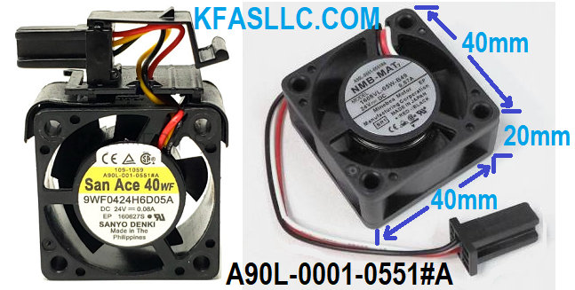
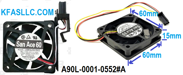
Cooling Fans
A90L-0001-0551#A
A90L-0001-0552#A
Cooling Fan Replacement Procedure
<1> Before replacing a fan unit, turn off the power to the CNC.
<2> Remove the fan unit to be replaced by holding the latch of the fan unit, and
pull the fan upward.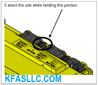
<3> Mount a new fan unit. (Push the fan unit in until the claw is latched into the case.)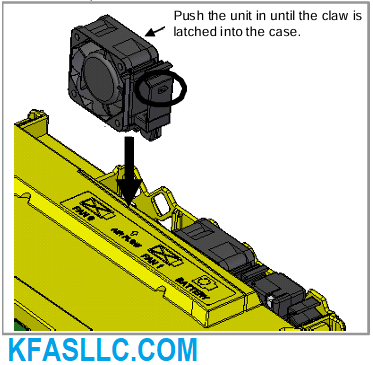
REPLACING BATTERY
Offset data, and system parameters are stored in SRAM in the control unit.
The power to the SRAM is backed up by a lithium battery mounted on the control unit.
This battery can maintain the contents of memory for about a year.
When the voltage of the battery becomes low, alarm message "BAT" blinks on the display.
When this alarm is displayed, replace the battery as soon as possible.
If the voltage of the battery becomes any lower, memory can no longer be backed up.
Turning off the power to the control unit in battery low state causes system alarm to occur because the contents of memory is corrupted.
Clear the entire memory and reenter data after replacing the battery.
Therefore it is recommended that the battery be replaced periodically, once a year, regardless of whether a battery alarm is issued.
Lithium Battery Replacement Procedure
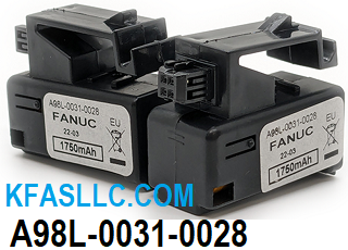
Prepare a new battery unit (ordering code: A98L-0031-0028).
(1) Turn on the power to the CNC. After about 30 seconds, turn off the power.
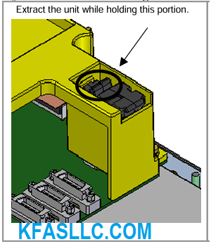
(2) Extract the old battery unit from the lower right of the rear of the CNC unit.
(Hold the latch of the battery unit, and extract the unit upward while releasing the claw from the case.)
(3) Mount the new battery unit. (Push the battery unit in until the claw is latched into the case.)
Ensure that the latch is engaged securely.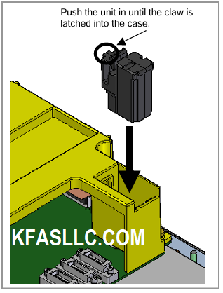


![]() © Copyright
KFASLLC Houston, Texas, USA
© Copyright
KFASLLC Houston, Texas, USA